AURORA MODEL MOTORING THUNDERJET 500 HO GAUGE - 1963 SERVICE MANUAL
FRONT COVER - PAGE 02
PAGE 03 - PAGE 04
PAGE 05 - PAGE 06
PAGE 07 - PAGE 08
PAGE 09 - PAGE 10
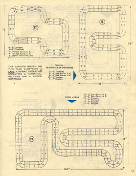
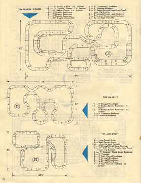
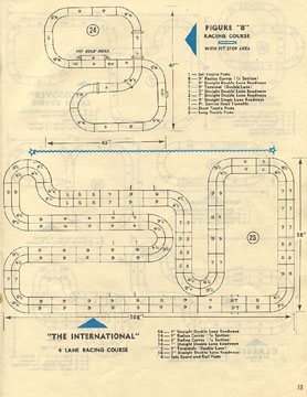
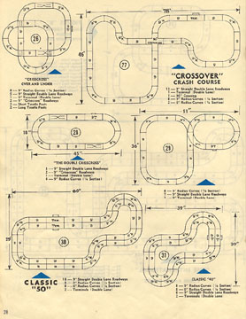
PAGE 11 - PAGE 12
PAGE 13 - PAGE 14
PAGE 15 - PAGE 16
PAGE 17 - PAGE 18
PAGE 19 - PAGE 20
PAGE 21 - PAGE 22
PAGE 23 - PAGE 24
PAGE 25 - PAGE 26
PAGE 27 - PAGE 28
PAGE 29 - PAGE 30
PAGE 31 - PAGE 32
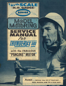
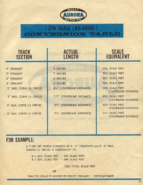
1/87th scale (H.O. Gauge) AURORA Model Motoring SERVICE MANUAL for Thunderjet 500 with the fabulous PANCAKE MOTOR - 1963 Aurora Plastics Corporation - West Hempstead, Long Island, New York Please... Before you try it your way... read manual and try it our way! (page 01)
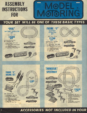
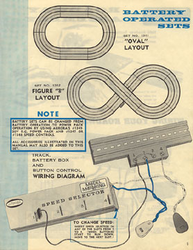
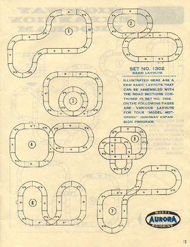
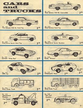
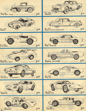
OVAL Battery Operated Set NO. 1311 $10.00 - FIGURE 8 Battery Operated Set NO. 1312 $12.00 - FIGURE 8 RACING SET NO. 1307 $19.95 - THUNDERJET SPEEDWAY Set NO. 1302 $24.95 (page 02)
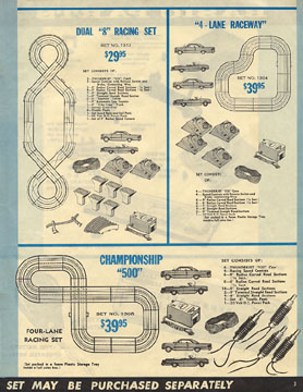
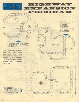
DUAL 8 RACING SET Set NO. 1310 $29.95 - 4 LANE RACEWAY Set NO. 1304 $39.95 - CHAMPIONSHIP 500 FOUR LANE RACING SET NO. 1308 NO. $39.95 (page 03)
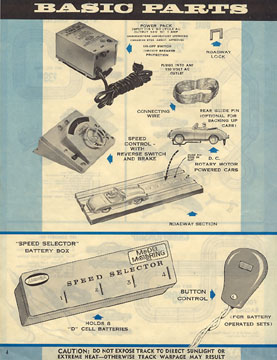
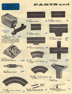
BASIC PARTS - POWER PACK - ROADWAY LOCK - CONNECTING WIRE - SPEEDCONTROL WITH REVERSE SWITCH AND BRAKE - REAR GUIDE PIN (OPTIONAL FOR BACKING UP CARS) - D.C. ROTARY MOTOR POWERED CARS - ROADWAY SECTION - SPEED SELECTOR BATTERY BOX HOLDS 8 D CELL BATTERIES - BUTTON CONTROL (FOR BATTERY OPERATED SETS) - CAUTION: Do not expose track to direct sunlight or extreme heat - otherwise track warpage may result (page 03)
BATTERY OPERATED SETS - Battery sets can be changed from battery operation to power pack operation by using AURORA'S #1349-20V D.C. Power Pack and #1347 or #1348 Speed Controls. TO CHANGE SPEED: Insert speed selector in any of the slots from 1 to 4. (When batteries start to run down, move to the next slot.) (page 04)
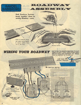
ROADWAY ASSEMBLY - Hold Roadway Sections firmly together when inserting Roadway Locks & Joiner Pins. Ends of Conductor Strips are under spring tension to assure contact from one to the other. WIRING YOUR ROADWAY - Cut wire to length required to suit your layout. Strip insultion from end of wire and connect to terminals as shown in diagrams. Loop bare wire around terminal post. (page 06)
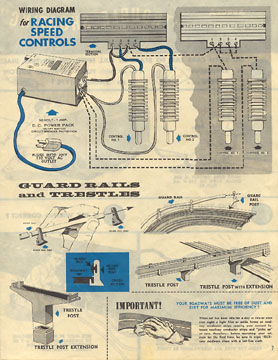
WIRING DIAGRAM FOR RACING SPEED CONTROLS - TERMINAL SECTION - CONTROL NO. 1 - CONTROL NO. 2 - CONTROL NO. 3 - CONTROL NO. 4 - 20 VOLT - 1 AMP D.C. POWER PACK ON-OFF SWITCH CIRCUIT BREAKER PROTECTION PLUGS INTO ANY 110 VOLT AC OUTLET GUARDRAILS AND TRESTLES - GUARD RAIL - GUARD RAIL POST - TRESTLE POST - TRESTLE POST WITH EXTENSION ROADWAY IMPORTANT! YOUR ROADWAYS MUST BE FREE OF DUST AND DIRT FOR MAXIMUM EFFICIENCY! When set has been idle for a day or two or even over night a light film or oxide forms on roadway conductor strips and picks up on cars, therefore before operating your set, even for the first time, be sure to wipe (RUB) your roadways clean with a lint free cloth. (page 07)
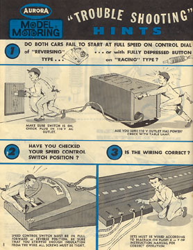
TROUBLE SHOOTING HINTS - (1) DO BOTH CARS FAIL TO START AT FULL SPEED ON CONTROL DIAL OF REVERSING TYPE OR WITH FULLY DEPRESSED BUTTON ON RACING TYPE? Make sure switch is on. Check plug in 1110V AC outlet. Are you sure 110V has power? Check with table lamp. (2) HAVE YOU CHECKED YOUR SPEED CONTROL SWITCH POSITION? Speed control switch must be in full FORWARD or REVERSE position. Be sure that you stripped enough insulation from the wire. All screws must be tight. (3) IS THE WIRING CORRECT? Sets must be wired according to diagram on pages 6 or 7 of instruction manual for operation. (page 08)
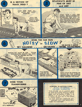
TROUBLE SHOOTING HINTS - (4) IS THE SECTION OF TRACK DEAD? Make sure that all U LOCKS are fully inserted. - (5) ROADWAYS MUST BE FREE OF DIRT AND LINT Clean with a lint-free cloth. This is important! Otherwise the dirt on the conductor rails will stop the cars pickup shoes from contacting the rail, and they will not run. (6) DOES THE CAR RUN NOISY OR SLOW? Try cleaning... Remove TOP PLATE of car... clean commutator, remove all dust, lint or foreign matter... and reoil. or oiling CAUTION: Do not over-oil, or maybe it needs wheel adjustment Hubs could be binding on chassis or tires rubbing against body. Remove lint from around the axles. (7) DOES YOUR TRANSFORMER HUM-M-M-M? That's O.K. - It's normal! (page 09)
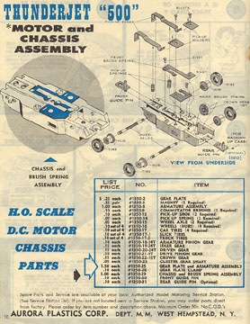
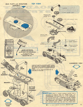
AURORA THUNDERJET 500 MOTOR & CHASSIS ASSEMBLY UNDERSIDE VIEW - RIVETS - PICK UP SHOES - PICK UP HOLDERS - FRONT BRUSH SPRING - PICK UP SPRINGS - FRONT GUIDE PIN - REAR BRUSH SPRING - CROWN GEAR (15 TOOTH) - WHEEL AXLES - HUB - TIRE - REAR GUIDE PIN (FOR BACKING UP CARS) (OPTIONAL RED) (page 10)
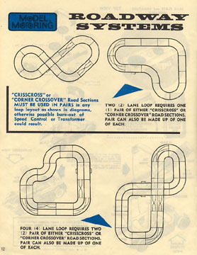
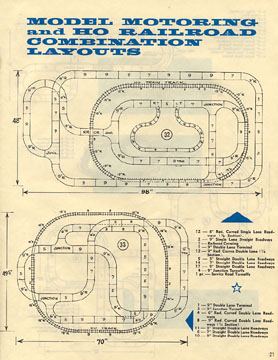
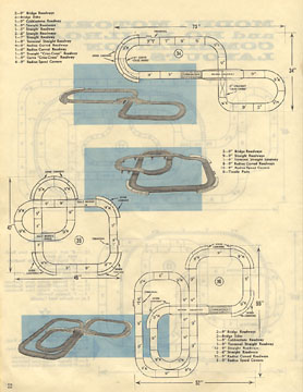
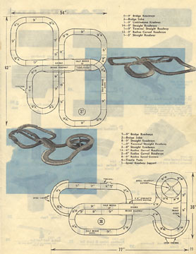
ROADWAY SYSTEMS - CRISSCROSS or CORNER CROSSOVER Road sections MUST BE USED IN PAIRS in any loop layout as shown in diagrams, otherwise possible burn-out or Speed Control or Transformer could result. Two (2) lane loop requires one (1) corner pair of either CRISSCROSS or CORNER CROSSOVER road sections. Pair can also be made up of one of each. Four (4) lane loop requires two (2) pair of either CRISSCROSS or CORNER CROSSOVER road sections. Pair can also be made up of one of each. (page 12)